⚗️ Manual for using STAMP
Setup for Testing Additively Manufactured Plugs
In case of emergency
- Immediately switch off the heater using the red and green power buttons on the heater controller (see Figure 6).
- If safe and possible, switch off supply of any flammable gases.
- Follow the relevant laboratory procedures described in Lab 10a: Alarm Systems.
- Inform Peter as well as Delf or Oliver or Kai.
1. Purpose
To supply NH3 (1%, 10%) in Ar to the reactor and utilize Xe as an internal standard, allowing the ammonia decomposition experiments to be carried out safely and reproducibly.
2. Requirements (Gases, Equipment and Software)
2.1 Gas Supply
The following gases are permitted for use:
- 1% NH3 / 99% Ar: 10 l cylinder in gas cabinet, e.g. concat:HRWJNA
- 10% NH3 / 90% Ar: 10 l cylinder in gas cabinet, e.g. concat:IPDUIJ
- 1% Xe / 99% Ar: 10 l cylinder in gas cabinet, e.g. concat:UBEDOH
- NH3 calibration gas: 10 l cylinder in gas cabinet, e.g. concat:LAZCGZ
- Ar, N2 (house gases)
- Forming gas (house gas, 10% H2 / 90% N2)
- A compressed air system (used for heating and gas wash)
2.2 Eqiupment
2.3 Safety & Analytical Devices
- Safety goggles (mandatory in order to work in the lab 10a)
- Personal NH3 sensor (Dräger)
- Drechsel-type gas washing bottle for trapping ammonia using water
- Respirator when handling catalyst powders
- Lab gloves while manipulating chemicals, powders and liquids
- Lab coat while manipulating chemicals
- Pipette
- Gas Chromatograph (GC)
2.4 Necessary software
- Bronkhorst software
- GC Software
- tomato
- marinara
3. Operating manual
3.1 Check gas safety
Please refer to the Manuals for work with the Gas Cabinet, NH_3 Cabinet as well as the Gas Bottles.
3.1.1 Bump test of the NH3 sensor (Dräger)
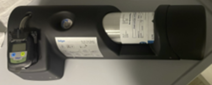
Check that the NH3 sensor (Figure 1) is working properly. You may not work with NH3 without a working NH3 sensor!
- Make sure the NH3-containing bottle is inserted into the bump test station (Figure 2) and the station is pressurized.
- Press and hold the two buttons on the NH3 sensor simultaneously to turn it on.
- Then, as shown in Figure 2, insert the sensor and press the lower part of the sensor.
- Keep pressing until the alarm sounds; once it sounds, remove the sensor.
- Depressurize the bump test station by unscrewing the bottle slightly.

If the NH3 sensor does not alarm, stop and inform Peter and Sunil.
3.1.2 Inspection of the gas connections
Check that all gas lines connected to the setup and the gas mixing system (Ar, NH₃/Ar, Xe/Ar) are properly connected. Follow the sequence shown below:
- Ensure that the purge gas outlets of the NH₃/Ar and Xe/Ar lines are closed.
- Verify that the NH₃/Ar and Xe/Ar gas cylinders are correctly connected to the gas lines inside the cabinet.
- Confirm that the NH₃/Ar and Xe/Ar gas cylinders are fully opened.
- Check that the service gas inlet valves for NH₃/Ar and Xe/Ar are open.
- Finally, ensure that the pressure gauge at the service gas outlet reads 5 bar.
WarningIf the service gas outlet pressure gauge for NH3/Ar or Xe/Ar is below 5 bar, stop and inform Peter and Sunil.
Switch on the main gas cabinet shut-off switch (see Alarm Systems: Figure 3) to allow the release of NH3 gas from the cabinet.
Confirm that the toxic gas caution light is on.
Open the wingnut shut off valves for the NH3/Ar and Xe/Ar pressure regulators on the wall and check whether the pressure gauge remains at the marked level.
WarningIf the pressure briefly increases and then drops to 0, immediately close the wingnut shut off valve for NH3/Ar again, and close the gas cabinet shut-off to fully shut off the NH3 gas. There is likely a leak on the line. Inform Peter and Sunil immediately.
Open the wingnut shut-off valve for Xe/Ar gas pressure regulator on the wall in the same manner. If the pressure on the gauge drops when opening the valve, close it again immediately and inform Peter and Sunil.
The wingnut shutoff valve for Ar gas should remain open, so simply check whether the pressure gauge is below the marked level.
3.2 Install NH3 gas washing bottle
3.2.1 Wash bottle
Material required:
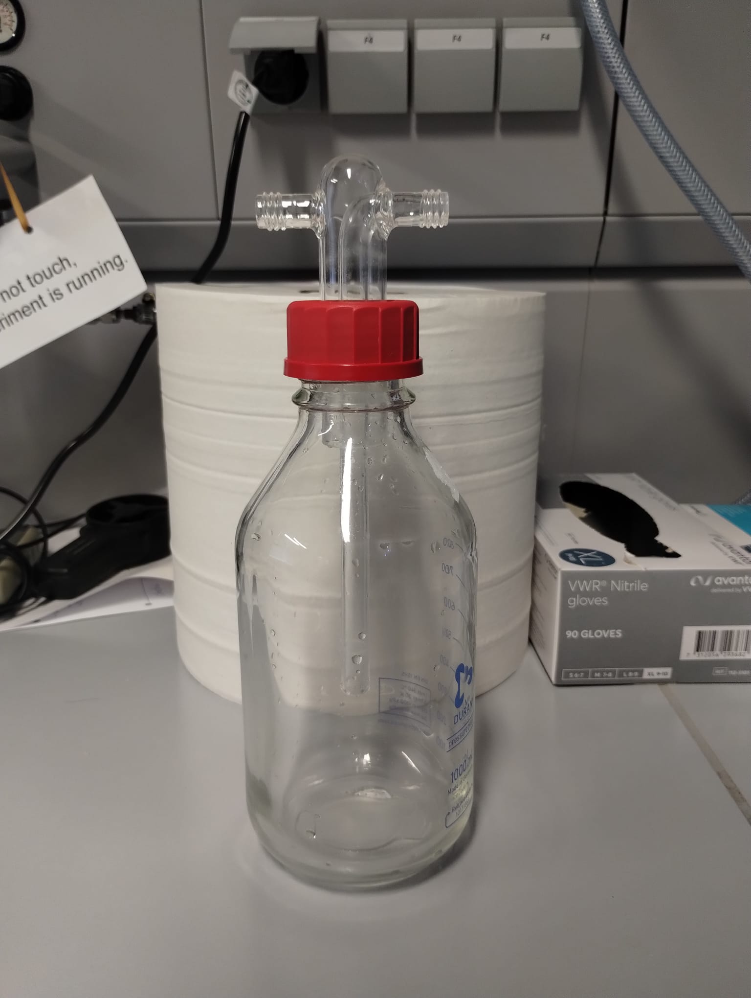
- Drechsel bottle (see Figure 3)
- Lab Coat
- Gloves (at least one)
- Phenolphthalein
- Pipette
Instructions:
- Add 800 ml of deionized water inside the 1 l Drechsel bottle.
- Add approx. 1 ml of Phenolphthalein.
- Close the Drechsel bottle and swirl it gently to homogenize the solution.
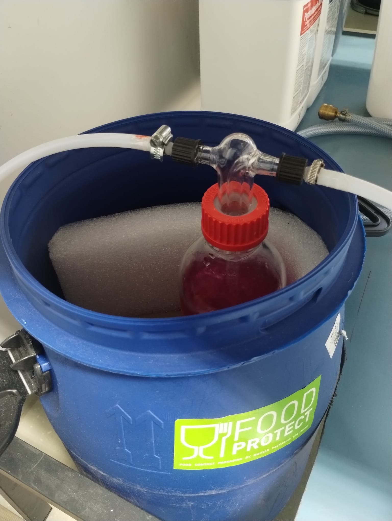
- Connect the setup outlet to the gas inlet of the bottle marked with the green label. See Figure 4.
- Connect the bottle outlet to the vent pipe marked with the red label.
- Then place the bottle inside the blue bucket.
Do not confuse the gas inlet and outlet of the bottle!
Check that the vent line is attached to the gas vent!
3.2.2 Compressed air supply
- Ensure the NH3 wash bottle is connected.
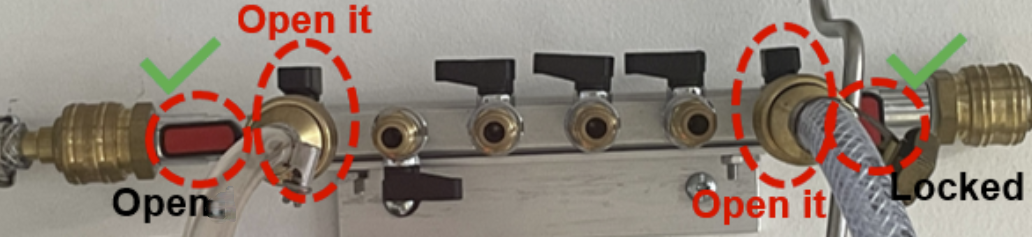
- On the compressed air system manifold, open the ball valves for outlets 1 and 6 counting from the left as shown in Figure 5.
- Ensure that the inlet to the manifold is open and the seventh outlet is always closed as shown in Figure 5.
This step lets the compressed air into the NH3 wash bottle and supplies air for heating up of our experiment.
3.3 Sample Loading
Material required:
- FFP2 Respirator, mandatory when handling catalyst powders
- Laboratory gloves
- Lab spatula
- Plastic weighing dish
- Reactor (powder and AM samples)
3.3.1 Powder Sample Preparation and Insertion
When handling powder samples, follow the safety measures specified in GBU Ebene 3 Gefahrstoffe.
- Weigh the empty reactor and record its weight.
- Insert glass wool into the bottom of the powder reactor until just before the tube widens and weigh the reactor again to determine the weight of the glass wool.
- Place a piece of weighing paper on the balance and tare it.
- Then weigh out 300 mg of the catalyst sample on the weighing paper (tolerance: +5 mg).
- Carefully transfer the catalyst sample into the reactor and weigh the reactor again to determine the weight of the catalyst sample.
- Then insert glass wool on the top of the powder until before the ridges of the reactor, ensuring that the catalyst is securely held in place. Weigh the reactor again to determine the weight of the glass wool on top of the catalyst sample.
- Insert the reactor into the reactor holder.
- Tighten the reactor holder properly.
- Create a sample ID on datalab and enter the weight of the catalyst sample, the weight of the glass wool, and the weight of the reactor under the corresponding sample ID.
3.3.2 AM Sample Preparation and Insertion
- Weigh the AM sample using a balance and record the weight.
- Create a sample ID on datalab.concatlab.eu and enter the weight of the AM sample under the corresponding sample ID.
- Place the AM sample into the reactor making sure that the flatter side of the sample is facing downwards.
- Then insert glass wool on the top of the AM sample.
- Insert the reactor into the reactor holder.
- Tighten the reactor holder properly.
3.4 Check heater controller
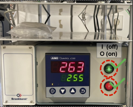
- Verify that the temperature controller (Jumo, see Figure 6) is switched on. If the temperature display does not appear on the temperature controller, stop the experiment and inform Peter and Sunil.
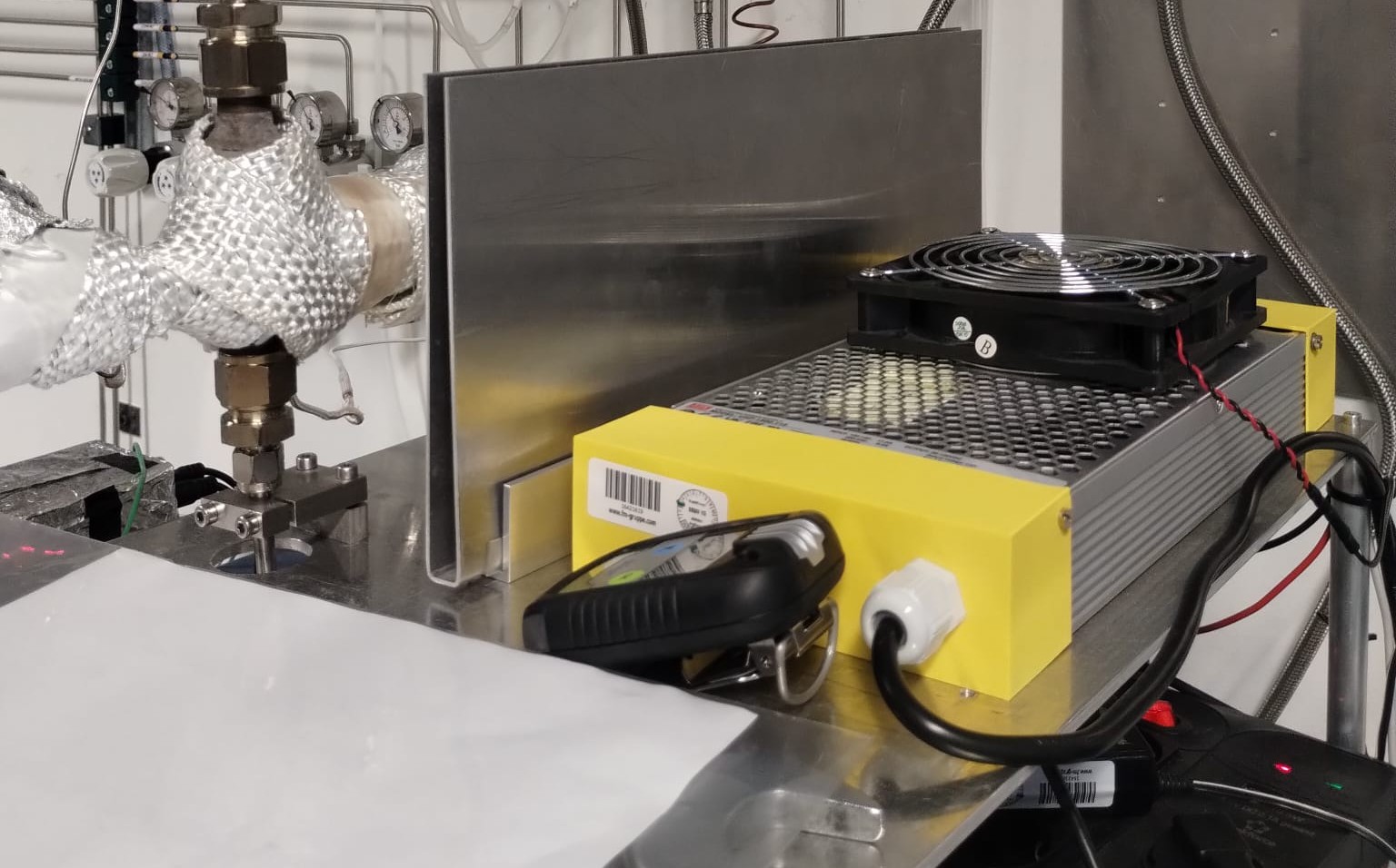
- Place a heat-shield plate between the reactor and the power supply as shown in Figure 7 to prevent the power supply from heating up.
3.5 Leak test of the reactor
Tools required:
- Bronkhorst flow and pressure controller, with the related software
- GC and the related software
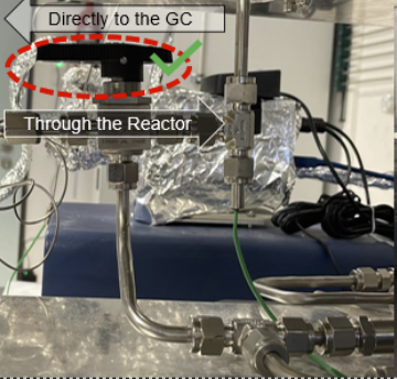
Before performing the reactor leak test, please check that the T-port valve is positioned toward the reactor as shown in Figure 8.
3.5.1 Check gas lines
- Verify that the Ar (house) gas line is connected to MFC-13.
- Verify that the Xe/Ar (cabinet) gas line is connected to MFC-12.
- Verify that the outlet of the mixer on the wall is connected to MFC-81.
- Verify that the NH3/Ar (cabinet) gas line is connected to MFC-82.
3.5.2 Purge
This is done using the Bronkhorst software after checking the gas lines:
- Open the Bronkhorst software.
- First, select
13/150.FG-201CSon the left hand side panel and then click the refresh button in the upper right corner. - Next, click the purge valve button and confirm.
- Then perform the same purge procedure for
81 FLOWand80 PRESSUREas you did for13/150.FG-201CS.
3.5.3 Measure O2 and N2 concentrations after purging
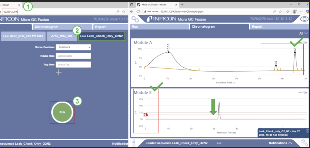
- Open the internet browser.
- Enter
10.10.1.12in the address bar and press Enter. - When the window appears as shown, click
Leak_Check_Only_O2N2and then click Run. - You will then see Module A and Module B displayed.
- Wait until the oxygen and nitrogen signals in Module A approach zero.
- Then wait until the signal in Module B decreases below 2k.
If the measurement remains above 2000 µV even after tightening, please stop the experiment and inform Peter and Sunil.
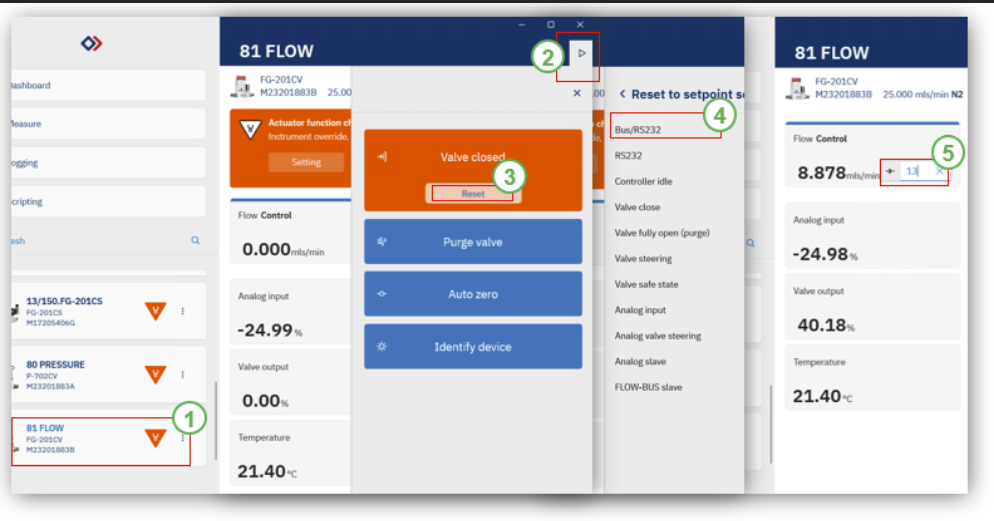
3.5.4 Leak test under low flow conditions
- Open the “Bronkhorst Flow Suite 2” as shown in the image below.
- Click on 81 Flow.
- Then click the refresh button in the upper right corner.
- In the “Valve closed” box, click Reset and then Confirm.
- After that, click BUS/RS232.
- Enter a flow rate of 15 and press Enter.
- Check whether the measured value in Module B falls below 2000 µV (If it is measured above 2000 microvolts, you must tighten the reactor holder).
If you cannot reach the desired values, or notice an increase, please inform Peter or Sunil immediately and do not pursue the experiment.
3.5.5 Setup the Xe/Ar gas inside the reactor
After successfully completing the leak test, wash the entire gas lines with Xe/Ar. You can set the flow rates for MFC12, MFC13, and PC-80 (80 Pressure) in the same way as shown in the figure above. From step 5 onward, please refer to the following figures and proceed accordingly.
- Set the MFC-12 (Xe/Ar) to a flow of 25 mL/min.
- Set the MFC-13 (Ar) to a flow of 0 mL/min.
- Set the PC-80 to a pressure of 1.9 bar.
- Check that the signal in Module B reaches to -10k µV as follows.
- Once you reach this peak, you can stop the GC.
- Using the Bronkhorst software, make sure all MFCs are closed.
- Close the Bronkhorst software.
3.6 Starting the experiment with tomato
Log in to the lab PC, install Anaconda on your computer, and create a conda environment in which tomato will be installed, for more information, please on how to set up a virtual envirnment please read the introduction to the git tutorial
Once tomato is successfully installed on your device, you may proceed with the remaining steps of the SOP. If the installation is not completed successfully, please inform Peter and Sunil.
- Open the folder on your computer.
- Create a new folder as shown in the image below.
- Name the new folder using the format: date and sample name.
- Then copy the appropriate .yml protocol files for the experiment and paste them into this folder.
- Right-click inside the folder and open a terminal.
After opening the terminal, please enter the following commands in order as shown below.
- Enter “conda activate tomato-stamp”, then enter “tomato start”.
- After that, press Ctrl + Alt + Del and open the Task Manager to verify that three tomato processes are running.
- If any of them are not running, enter “tomato stop” and then reboot the computer.
- Next, enter “ketchup submit ‘protocol_FileName.yml’”.
- Then enter “ketchup status” to verify that the status is qw.
- After that, enter “tomato pipeline ready stamp”.
- Enter “ketchup status” to confirm that the status has changed to r.
- While the experimental protocol is running automatically, log in to datalab.concatlab.eu as shown below and create a sample ID. Use the ORCID or GitHub ID that you created during onboarding.
- After logging in, create the sample ID according to the sequence shown in the images: in Step 2, enter the sample name, sample type, and setup version (e.g., SampleName_powder_Setup_v3); in Step 3,
- Copy the previously saved sample ID and click the Create button; in Step 5,
- click the X icon to delete the previous sample weight, and in Step 6, press the plus button and enter the InventStore ID to input the sample weight used for the test (the InventStore ID can be checked in InventStore); then, as shown in Step 7, remove all previously copied files; finally, press Save and copy the sample ID shown in Step 9.
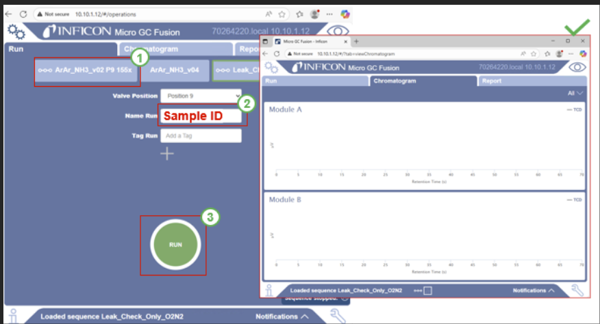
3.7 Start the GC
- Access GC in the browser as shown in the image below.
- Select the corresponding method.
- Enter the sample ID provided by datalab.concatlab.eu.
- Click Run and then Monitor Module A and Module B to observe whether the oxygen and nitrogen signals decrease and whether the xenon gas is detected.
3.8 Monitoring using marinara
- Open Marinara as shown in the image below.
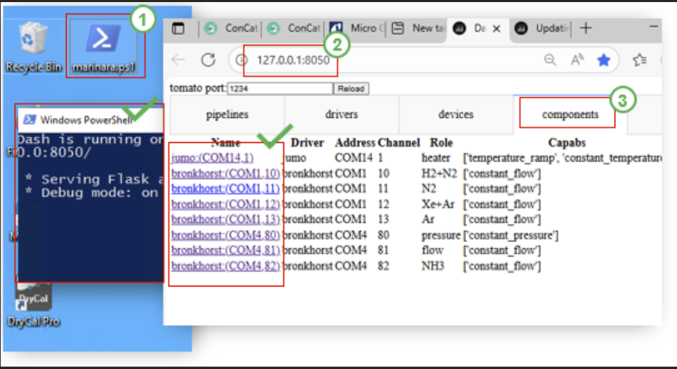
- When the blue window appears, access 127.0.0.1:8050 through your browser. If an error appears, click the address again and press Enter.
- Click Components, select Jumo, and check whether the setpoint temperature matches the actual temperature. Click COM13 to verify that the setpoint flow rate matches the actual flow rate. Click COM80 to check that the setpoint pressure matches the actual pressure.
- After 15 minutes, repeat the same checks to confirm whether the temperature, pressure, and the relevant gas flow rates have changed.
When the monitoring is finished, prepare the experiment progress and post it as shown below on the front of the setup and outside the laboratory.
3.9 Removing catalyst
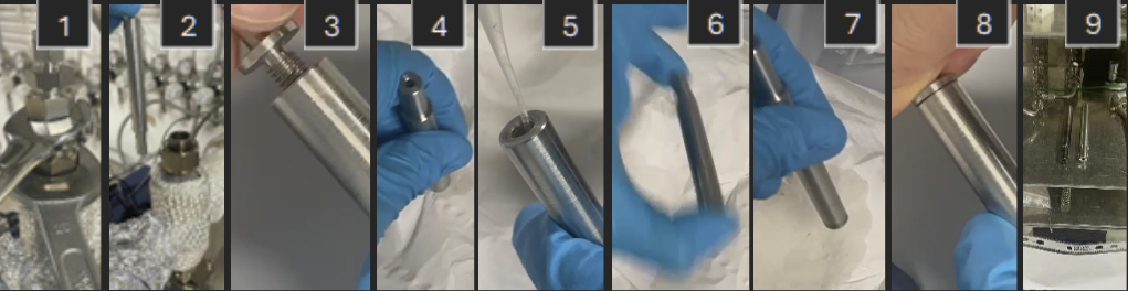
Follow instructions from Figure 13:
- Loosen the nuts using the 25” and 24” wrench, taking care to use heat-resistant gloves if the instrument is still hot.
- Measure the weight of the reactor after taking it out of the setup
- Take out the glass wool (measure the weight at this point) and the sample from the sample case (label the sample and store it in the designated sample vial).
- Clean the reactor with acetone and cotton buds.
- Enter the weight of the reactor, glass wool, and sample into datalab under the corresponding sample ID.
3.10 Neutralizing the wash bottle solution
- Close the compressed air manifold, closing the lines shown in Figure 5.
- Open the NH3 wash bottle outlet and hold the NH3 sensor (Figure 1) close to it for about one minute.
- If no alarm is triggered, disconnect the gas inlet hose to the NH3 gas wash bottle and add diluted hydrochloric acid until the pink solution becomes completely colourless, thereby neutralizing it.
- Dispose of the neutralized solution in the sink in the Lab 10C, rinse with water, and place all components back in their original positions.
4. Shutdown
The following steps should be performed in continuation to the steps in the previous section:
- Turn off the heater and completely shut down the power supply of the setup, including the installed power strip.
- Close all gas supply wingnut valves except for Ar (i.e., NH3/Ar and Xe/Ar).
- Fully shut off the NH3/Ar gas supply using the central gas cabinet power switch.
- Close the NH3/Ar and Xe/Ar gas cylinders in the gas cabinet, and also close the service gas inlet.
- If the concentration of the ammonia bottle in question is higher than 10%, remove the ammonia gas bottle according to the procedure Removal of existing bottles