🗄️ Manual for Gas Cabinet Operation
Ventilated gas cabinet in Lab 10a
In case of emergency
- Emergency services:
- 030 314 2 3333 or 112
- First-aiders:
- Delf Kober
- Andreas Strasser.
- Lab responsible:
- Peter Kraus: 030 314 77803
- Switch off any heating and electrical equipment in the lab to minimize fire risk.
- If possible, close the cabinet.
- Ensure lab air exchange system is on.
- Leave the lab immediately.
- Follow the relevant laboratory procedures described in Lab 10a: Alarm Systems.
- Inform Peter as well as Delf or Oliver or Kai.
1. Purpose
This document supplements the valid BA: Gasflaschenschrank by detailing instructions for:
- Routine work with the ventilated gas bottle cabinet inside Lab 10a.
- Installation and removal of bottles from the gas bottle cabinet.
- Safe work with carbon monoxide (CO) and ammonia (NH_3) bottles.
2. Risks
- Life-threatening / Toxic / Harmful substances when inhaled
- Danger of asphyxiation due to lack of oxygen
- Danger of fire due to highly flammable gas
- Risk of injury due to gas escaping under high pressure
- Risk of to cold burns due to expanding gases
- Risk of explosions due to of heat or fire
- Risk of injury during mechanical work during transport and installation
2.1 Gases
The following 10 l gas cylinders are installed in the gas cabinet:
- CO/N_2 line: calibration gas containing 500 ppm CO; toxic
- CH_4/N_2 line: 20% CH_4 in N_2; flammable
- C_2H_6/N_2 line: 20% C_2H_6 in N_2; flammable
- C_3H_8/N_3 line: 20% C_3H_8 in N_2; flammable
- NH_3/N_2 line: calibration gas containing 500 ppm NH_3 and 2% N_2 in Ar; toxic
- NH_3/Ar line: 1% NH_3 in Ar; toxic
- empty yellow line
- Xe / Ar line: 1% Xe in Ar
3. Operating manual
- Always use mobile gas sensors when working with CO or NH_3
- Storage of gas mixtures with CO content over 500 ppm is not allowed
- Storage of gas mixtures with NH_3 content over 1 vol% is not allowed
- When changing bottles:
- An accompanying person must always be present outside the laboratory.
- Always open the window.
- Always check the valves of filled and empty gas bottles for leaks.
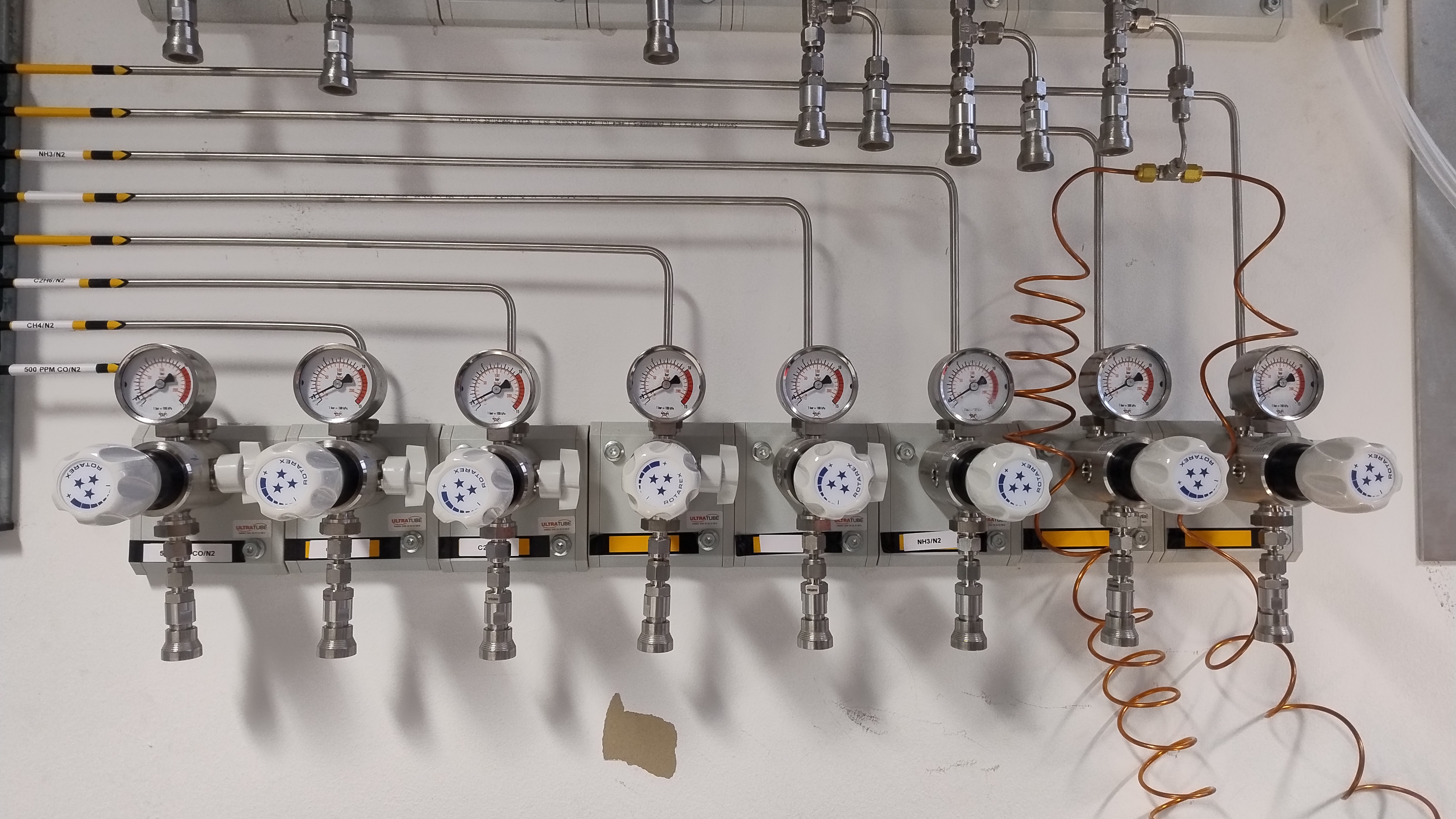
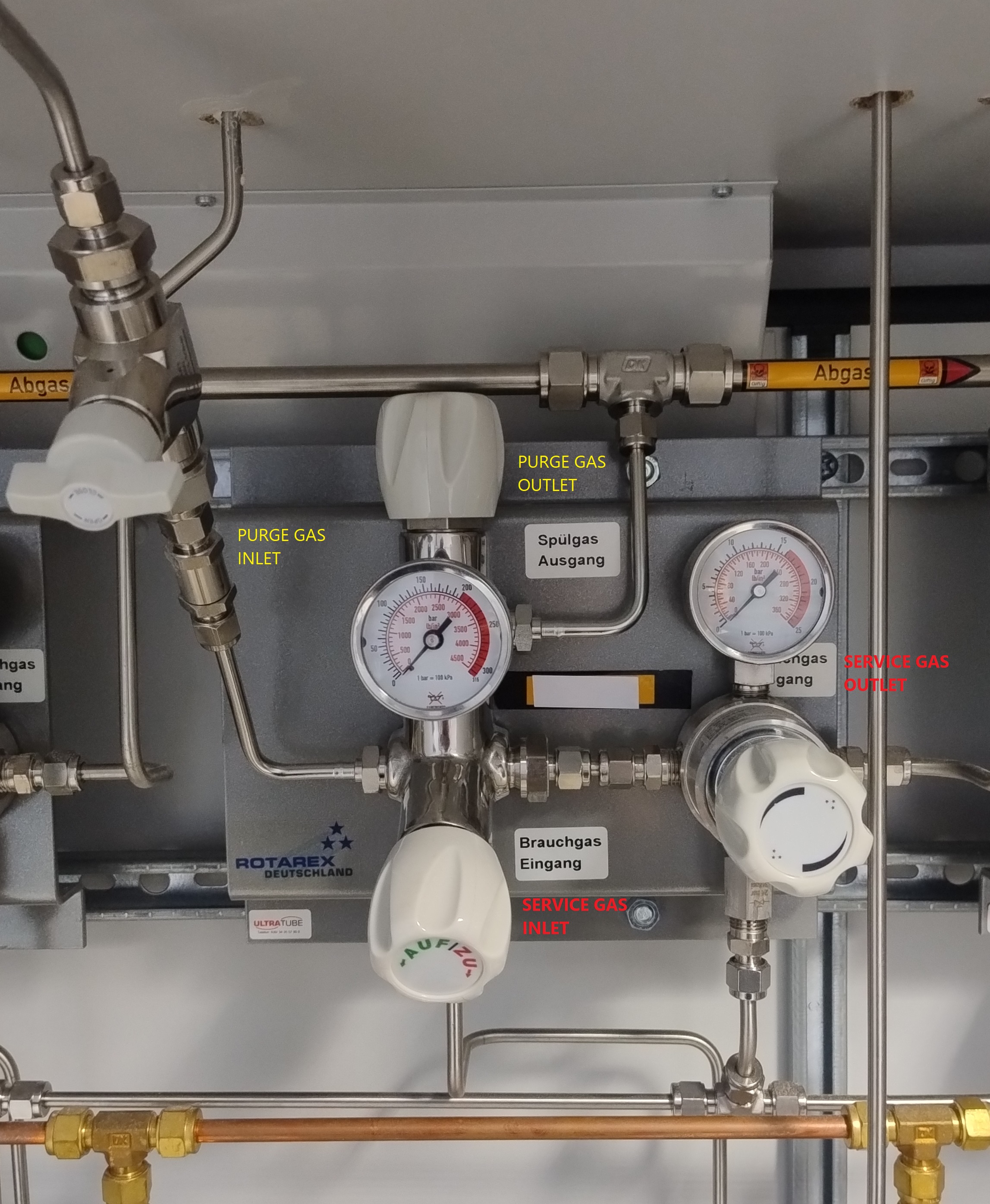
Operation of connected bottles
- Always assume that lines allocated to CO and NH_3 are pressurised with toxic gas:
- Never open the wingnut valve on the pressure reducer on the wall (see Figure 1) without an appropriate vent line attached.
- Do not disconnect any lines that may contain CO or NH_3 without purging them with purge gas for at least a minute first.
- At the end of every experiment:
- Close the wingnut valve on the pressure reducer on the wall.
If you know that a certain gas bottle is not likely to be used soon (e.g. in the next month), follow the instructions for removal of bottles until point 13. Leave the bottle attached. Note the bottle status in the Lab Log.
If a bottle has not been used for a month (see Lab Log), proceed with installation of bottles from point 4. onwards. Note the bottle status in the Lab Log.
Removal of existing bottles
- Familiarise yourself with the
🧴 Manual Gas Bottles. - Follow these steps:
- Ensure the wingnut valve on the pressure reducer on the wall is closed (see Figure 1).
- Attach the pressure reducer on the wall into a suitable vent.
- Close the gas bottle inside the cabinet.
- Open the purge gas outlet (see Figure 2). This will depressurise the line.
- Open the purge gas inlet (see Figure 2). Let the purge gas clean the valve for a few seconds.
- Close the purge gas outlet.
- If necessary, switch on the solenoids on top of the cabinet using the gas cabinet shut-off.
- Ensure the pressure reducer on the wall is still attached into a suitable vent.
- Open the wingnut valve on the pressure reducer on the wall (Figure 1). Purge the whole line for a minute.
- Close the pressure reducer on the wall using both the wingnut valve and the pressure regulator.
- If you switched on the solenoids, switch them off again.
- Close the service gas outlet (see Figure 2).
- Close the purge gas inlet (see Figure 2).
- Open and close the purge gas outlet to depressurise.
- Close the service gas inlet (see Figure 2).
- Disconnect the bottle. Attach bottle cap. Remove the bottle.
Installation of new bottles
- Familiarise yourself with the
🧴 Manual Gas Bottles. - Follow these steps:
- Do not open bottle until instructed to do so.
- Close all four valves in the gas cabinet (shown in Figure 2).
- Attach a vent line to the pressure reducer on the wall (see Figure 1).
- Vent the pressure reducer into a suitable vent.
- Insert and secure the bottle. Remove bottle cap and attach the line. Do not open bottle.
- Open purge gas inlet (see Figure 2).
- Open service gas inlet (see Figure 2). Do not open bottle.
- Open purge gas outlet for several seconds to purge the valve. Then close the purge gas outlet.
- Set service gas outlet pressure (see Figure 2) to approx. 5 bar.
- If necessary, switch on the solenoids to allow the purge gas to reach the pressure reducer on the wall.
- Ensure the pressure reducer on the wall is still attached into a suitable vent.
- Open the wingnut valve on the pressure reducer on the wall. Set the pressure regulator to appropriate pressure. Purge the line for a minute.
- Close the wingnut valve on the pressure reducer on the wall. Disconnect the vent line.
- Close the purge gas inlet.
- Open the bottle.
- The line will have to be flushed again as it still contains purge gas.
For installation of bottles with the same nominal composition, please make note of the act in the Lab Log. Ensure the new bottle is also present in the datalab inventory.
For installation of bottles with a new composition, follow the above instructions and also ensure correct labelling of pipes both inside as well as outside of the cabinet.