💨 Lab 10a: Gas Systems
General instructions
- Always work with the lab air exchange system on.
- Discuss the purchase/introduction of any new gases with Peter.
- Always check the lower and higher explosive limits (LEL and HEL) of any combustible gas you are working with (including hydrogen, ammonia, carbon monoxide, alkanes, alkenes). Work with any combustible gas is only permitted below the LEL or above the HEL.
- Document any changes and events in the Lab Log.
After finished with gases, make sure you close the wingnut valves on the pressure reducers on the wall for house lines (exception: argon), gas cabinet lines (see 🗄️ SOP: Gas Cabinet), and the compressed air system.
House gas lines
Connections to the following gas supply lines are installed in Lab 10a:
- Reserve line, currently used for Helium
- Synthetic air, 20.5% O_2 in N_2
- Propane (not connected)
- Carbon dioxide
- Argon
- Oxygen
- Nitrogen
- Forming gas, 10% H_2 in N_2
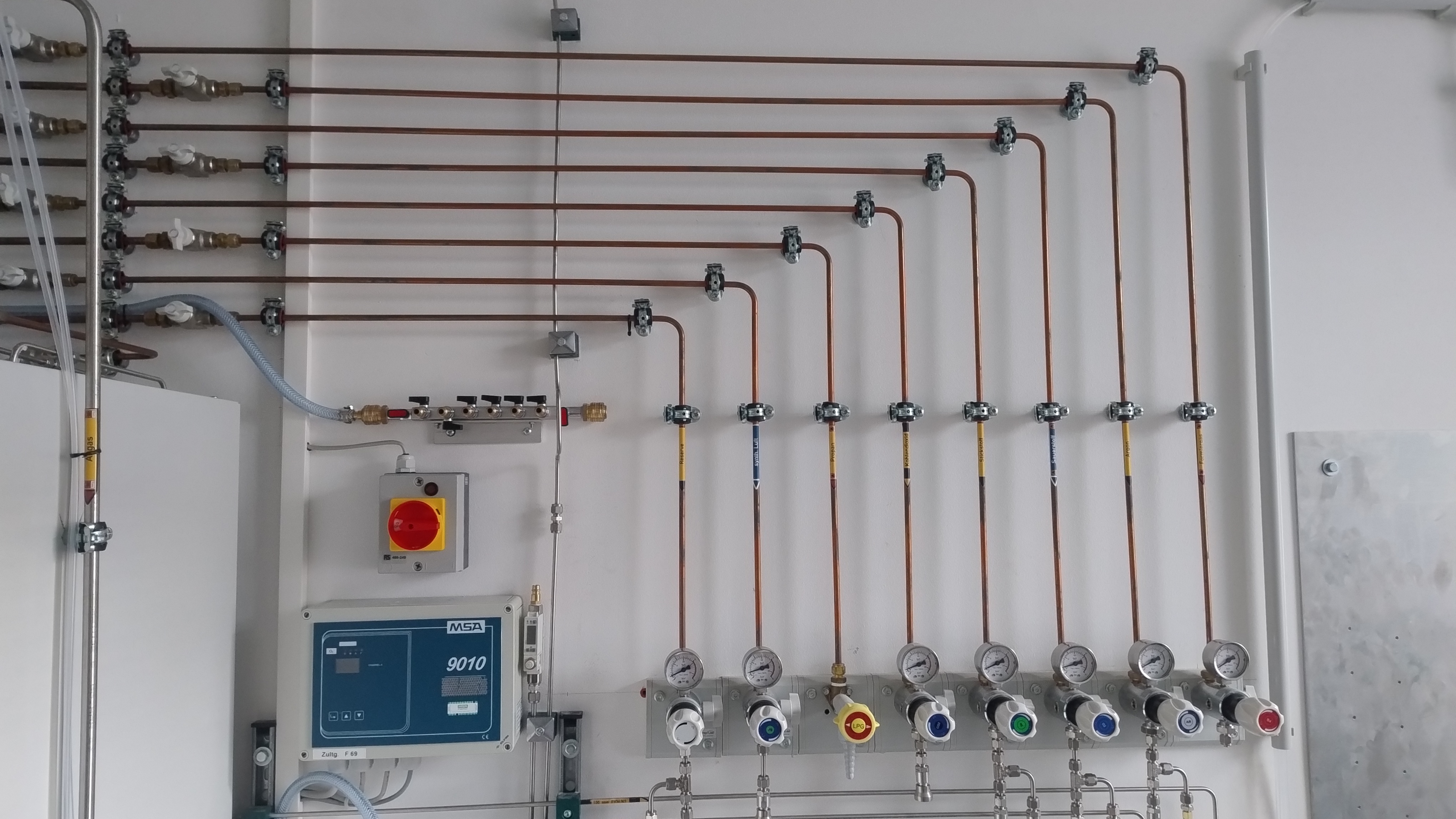
Each of those lines contains two shut-off valves (“wingnut valves”) as well as a pressure reducer:
- The first set of wingnut valves (upper left of Figure 1) are open when parallel with the piping. Do not open those unless authorised by Peter.
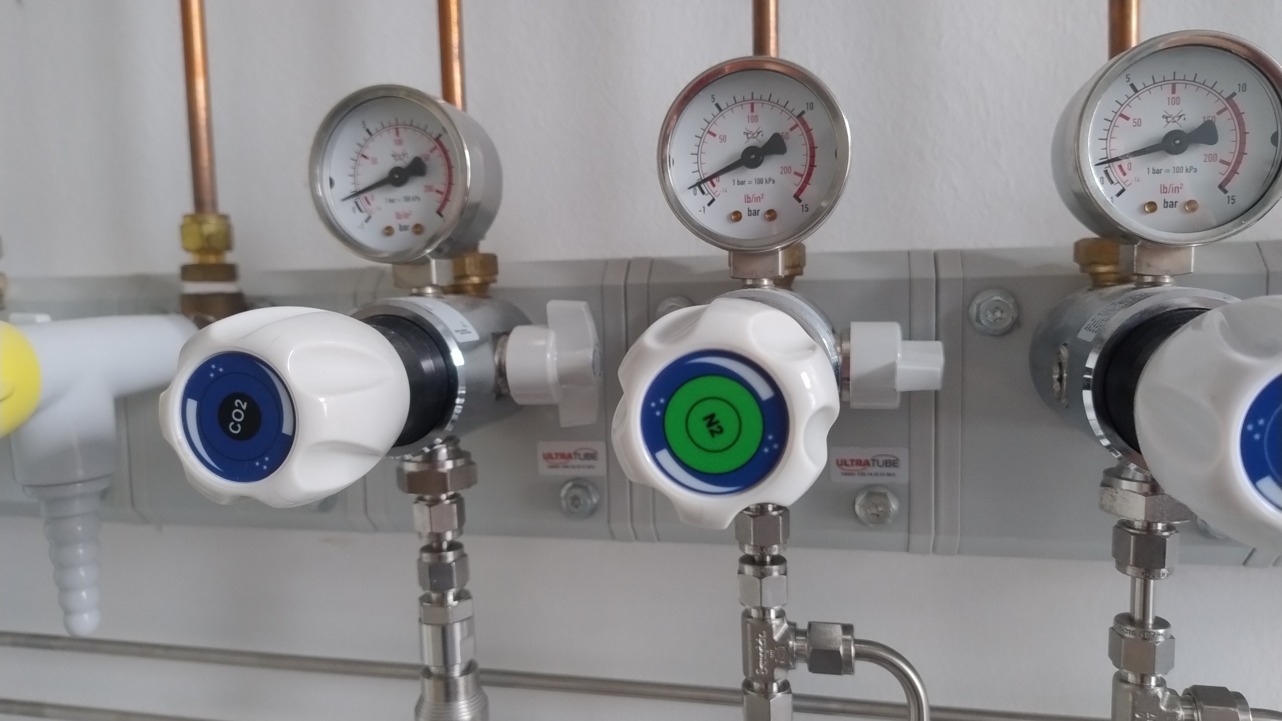
- The second set of wingnut valves are open when aligned with the body of the pressure reducers, as shown by the N_2 valve in Figure 2. Close these wingnut valves whenever the gas is not in use.
- Use the pressure regulator to reduce the pressure from the house line down to the required level.
The argon line is supplying the gas chromatograph. Do not close the wingnut valve while the gas chromatograph is turned on.
For house lines (as well as gas cabinet lines), the standard pressure we use is 4 bar when connected to a mixing station. Do not increase pressure above 4 bar. When connected to an instrument line directly, a lower operating pressure (\sim 2 bar) might be necessary.
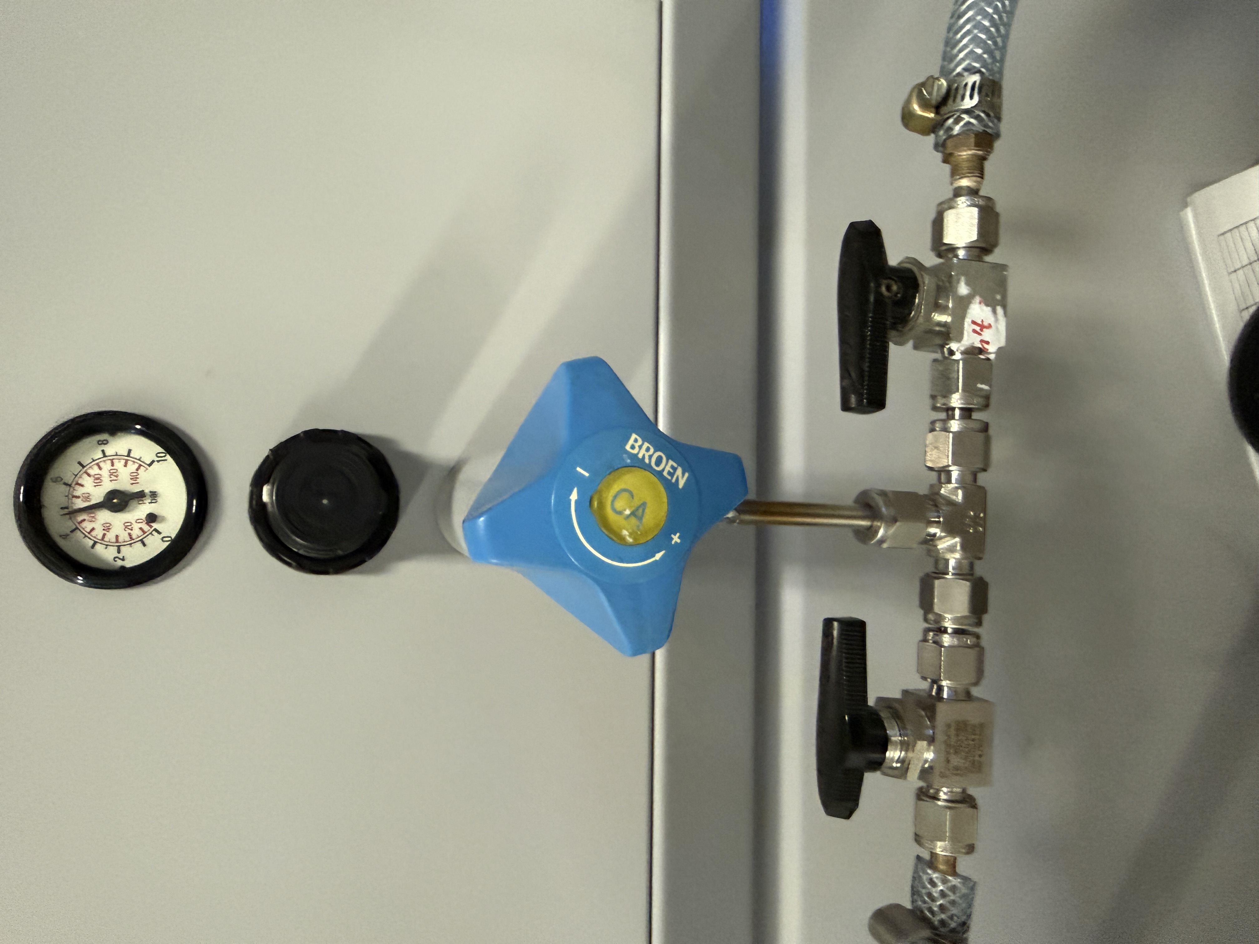
Compressed air system
A compressed air system, supplied by a compressor in the basement, is installed in the lab. The supply in Lab 10a is switched on or off using a main valve, and then controlled using the set of valves shown in Figure 3, where the pressure of the air and supply to either of the lab benches can be controlled.
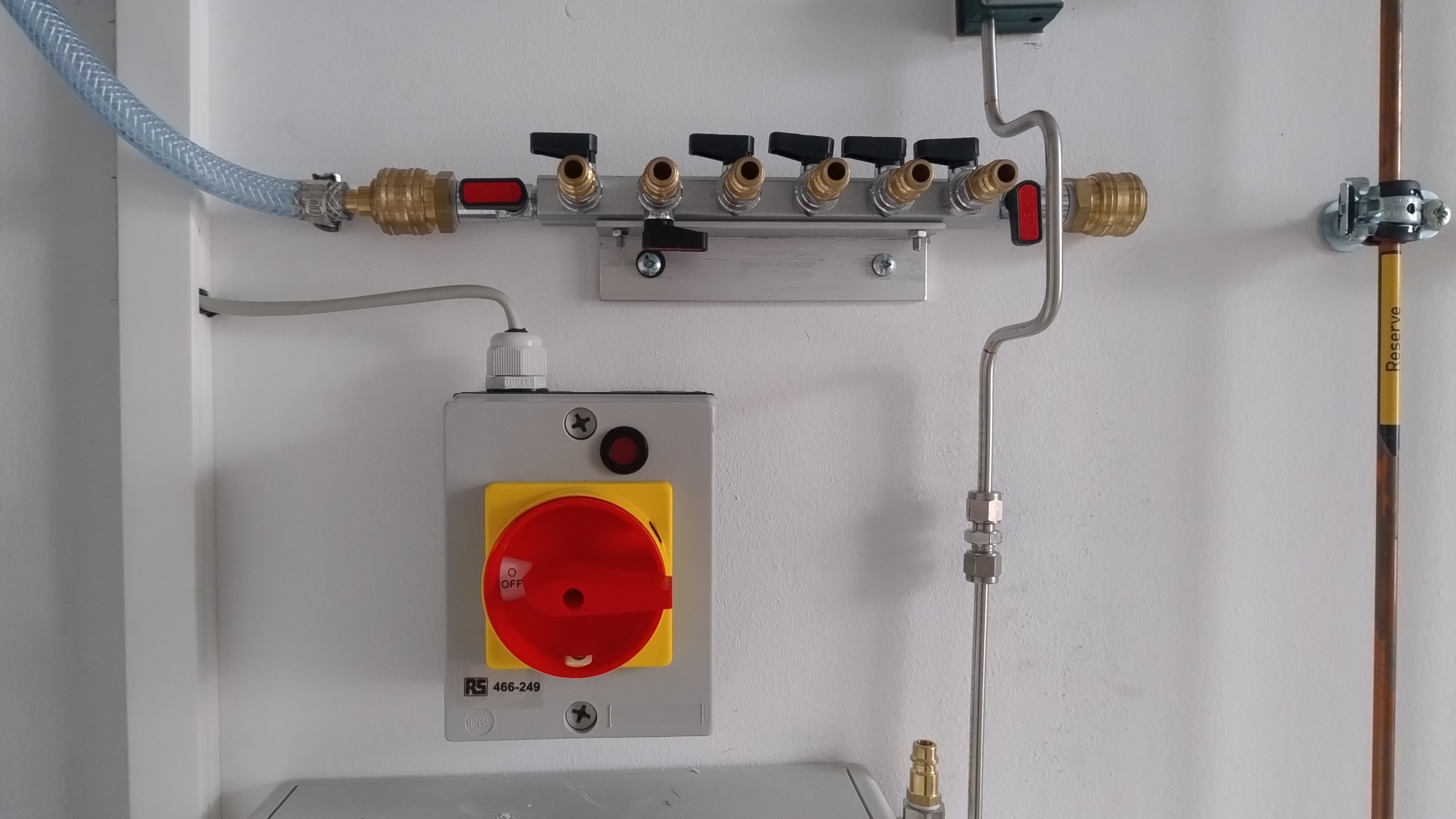
A manifold attached to the right supply ball valve is connected to a compressed air manifold on the other wall of the lab, located under the house line piping (see Figure 1). Detail is shown in Figure 4. The inlet to the manifold and each of the 7 outlets is equipped with a ball valve: in the configuration shown, the manifold is pressurised (the leftmost valve is open), but each of the outlets is closed.
The male DN 7.2 connectors are open. Therefore, hose connections between the manifold and instrumentation should be female-to-female, as the hose will hold the pressure after disconnect. Spare connectors (both male and female, also called “NW 7,2 mm Standard” in German) should be in the pump equipment drawer.
The air from this system can be used as process air, that is for heating, blowing, and valve actuation purposes. It’s not chemically pure, therefore it should not be used for applications where the air comes into contact with samples. For such applications, use the bottled synthetic air from the house line instead.
Gas cabinet lines
See the 🗄️ Manual Gas Cabinet, 💀 Manual NH3 Cabinet and 🧴 Manual Gas Bottles before working with gas bottles or with either of the gas cabinets.
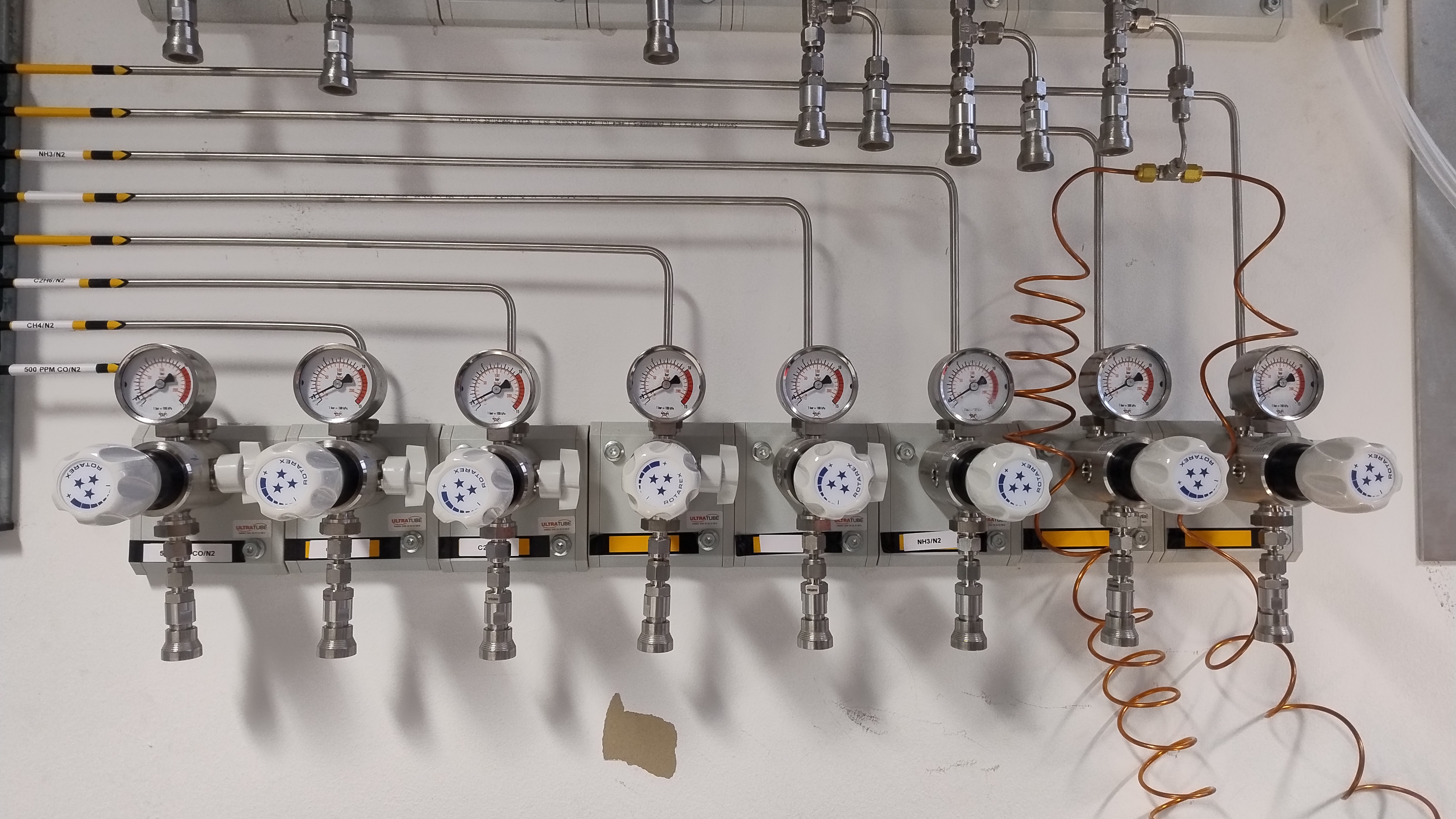
A ventilated gas cabinet, with capacity for 8 x 10 l gas bottles, is installed in Lab 10a. Each of the 8 lines can be individually purged by nitrogen and vented safely, and connected to pressure reducers shown in Figure 5. Three of those 8 lines are fitted with a magnetic shut-off valve (solenoid), which will stop the supply of that gas on power loss and in emergencies. Bottles containing toxic gases, such as ammonia (NH_3) and carbon monoxide (CO), can only be installed into those three lines. The following gases are currently installed (shown left to right in Figure 5):
- CO/N_2 line: calibration gas containing 500 ppm CO; toxic
- CH_4/N_2 line: 20% CH_4 in N_2; flammable
- C_2H_6/N_2 line: 20% C_2H_6 in N_2; flammable
- C_3H_8/N_3 line: 20% C_3H_8 in N_2; flammable
- NH_3/N_2 line: calibration gas containing 500 ppm NH_3 and 2% N_2 in Ar; toxic
- NH_3/Ar line: 1% NH_3 in Ar; toxic
- empty yellow line
- Xe / Ar line: 1% Xe in Ar
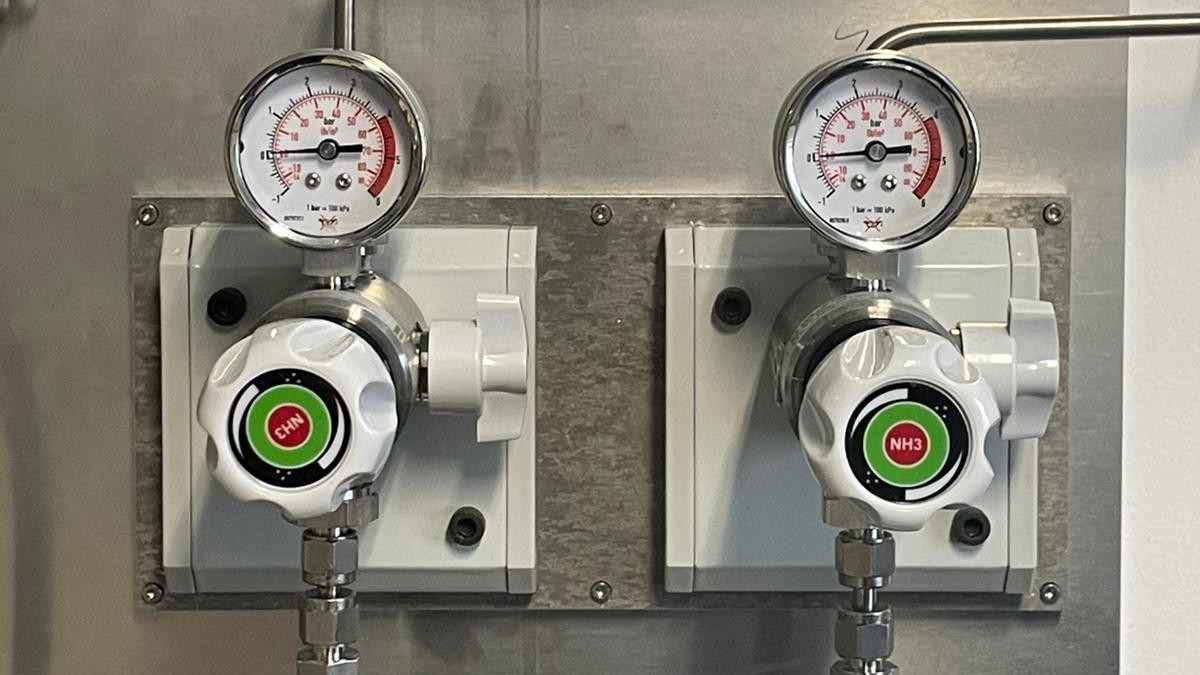
An external gas cabinet, with capacity for 3 x 50 l gas bottles, is installed behind building BA. Two lines connect the cabinet with the lab, as shown in Figure 6. Each of the lines is equipped with a solenoid. These lines are indended for use with toxic gases, purged using an argon bottle. The following gases are currently installed in the cabinet:
- argon, used as purge gas only
- NH_3 line; 100% NH_3 toxic, flammable
- a reserve line; not used
Lines marked with blue in the lists above are equipped with a solenoid, which means they will be shut when the gas cabinet shut-off is triggered.